Fusion 360 now has an experimental CAM feature to develop cutting paths for a laser cutter. I recently experimented with this feature, and thought I’d write up my findings.
These notes apply to our EXLAS 1280 laser cutter, which is driven by Lasercut 5.3 and accepts a DXF file as input. For non AMT readers, our laser cutter seems to be very similar to the RL-80-1290 sold by Rabbit Laser.
Background
It’s always been possible to use Fusion 360 to develop projects for our laser cutter. Taylor demonstrated it at one of his Fusion 360 workshops, and I’m sure more information can be found with a web search. Broadly, these are the steps:
- Model your project as for any other media. Arrange bodies into ‘components’ as appropriate.
- Copy each body to be laser cut to a new component called ‘cut layout’ or similar. Arrange the parts as desired, generally to minimize waste.
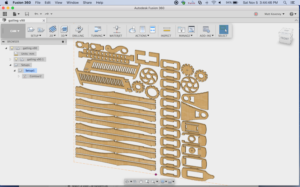
- Create a new sketch and project all parts on the cut layout to the sketch plane.
- Export this sketch as a DXF file.
The principal shortcoming of this approach is that the projected contours aren’t adjusted for the kerf of the laser cutter. Sometimes this doesn’t matter, but for parts that must precisely fit together (like the ubiquitous finger-jointed boxes) it can be an annoying problem.
We can adjust for kerf by doing some additional work right before exporting:
- Edit the cut-layout sketch; Select each profile in turn and:
- Apply the ‘offset’ tool, creating a new profile just outside the original. (For holes, offset inward.)
- Select the original profile and delete it. (It’s probably smart to make a copy of your cut layout sketch first).
- If you want ‘tabs’ to keep the pieces in the material sheet, they must be manually created: delete a small portion of the path at each desired location. I like to draw a small circle where I want the tab; use the ‘trim’ tool to delete the portion within the circle; then delete the circle.
Obviously, this is a major pain in the neck to maintain. If you didn’t get the kerf adjustment right the first time, or if your part dimensions or layout change, you must repeat these laborious steps. It’s an obvious application for a script or add-in, and I suspect something’s available but haven’t looked for it yet. Please post if you have an alternate technique!
Setting up for CAM
The new CAM support promises to address these shortcomings in a way that works more like the CAM workflow for milling or ‘CNC routing.’ To use it there are a few preliminary steps that must be done just once. These steps may become unnecessary when the feature passes out of the preview phase.
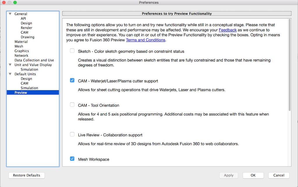
First turn the feature on: select ‘Preferences’ under your user name in the upper right corner. Then select ‘Preview’ and turn on ‘CAM – Water/Laser/Plasma cutter support.’
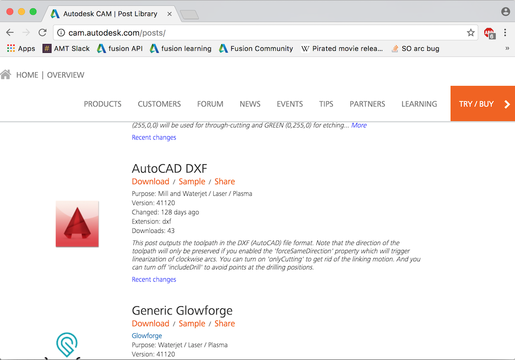
Next, install the DXF ‘Post Process.’ This allows saving the tool path as a DXF file.
- Browse here: http://cam.autodesk.com/posts/
- In the ‘type’ dropdown, choose ‘Water / Laser / Plasma’
- Then scroll down to ‘AutoCAD DXF’ and click ‘download’
- Save the ‘dxf.cps’ file to your machine.
- Install this post processor in your Fusion environment. On a Mac, you simply copy it to this directory:
/Users/<username>/Autodesk/Fusion 360 CAM/Posts
I’m sure there’s an equivalent on Windows. Please leave a comment if you figure out where it is.
Alternatively, you could also follow these steps, which put the post processor in the cloud so you can use it from multiple machines.
Creating the CAM tool path
You’ll probably still want to create the ‘cut layout’ component as described above. The CAM support does nothing to help with this step. (…Another obvious application for a custom script or add-in.)
Then, with the cut layout component visible and other components hidden,
- Enter the CAM workspace (the big gray menu on the left).
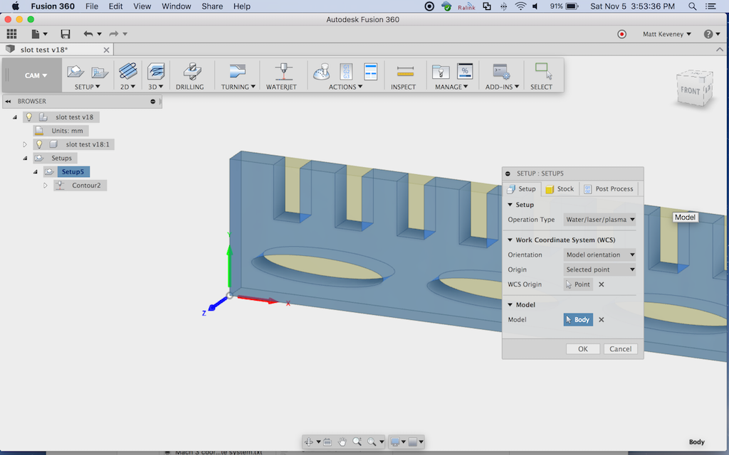
- Select ‘New Setup’ and set values as follows:
- On the ‘Setup/Operation Type’ tab, choose ‘Water/laser/plasma’
- On the ‘Stock’ tab, I prefer to use ‘relative size box’ with all offsets set to zero. You could also enter your actual stock size if desired, but this merely serves as a visual reference; perhaps as a double-check of your part layout.
- I like to set WCS to ‘model orientation’, ‘stock box point’, and then choose the lower-left corner of my stock box as illustrated here. This works the same as for milling operations.
- Click OK to finish the setup, then click ‘WATERJET’ to create a new contour operation, and set values on each tab as follows:
- ‘Tool’ tab:
- Type: ‘Laser cutting.’
- cutting mode: ‘Through – auto’ (I’m not sure what this does but it sounds logical and worked for me).
- Kerf width: more on this later; choose .5mm for now.
- Feed settings: don’t matter in our case.
- ‘Geometry’ tab:
- Select the contours to be cut. It seems that these must be selected individually, which is a pain in the neck for a complex project. When selecting contours, note that a red arrow is displayed illustrating the cut direction. More on this later.
- You can also set up ‘tabs’ here, if desired.
- ‘Heights’ tab:
- These values don’t matter, since we’re going to remove the movement paths at post-process time.
- ‘Passes’ tab:
- Set ‘Sideways compensation’ to ‘Left’ and set compensation type to ‘in computer’.
- ‘Linking’:
- Turn off both ‘Lead-In’ and ‘Lead-Out’
Click OK.
The tool path should be generated immediately. Examine it carefully, and ensure that the paths are all outside the part. For holes, the paths should be inside.
This is what those red arrows are all about. Note that the middle elliptical hole in my example has the tool path incorrectly positioned. To fix it, edit the contour; choose the geometry tab, and click the arrow on the offending contour.
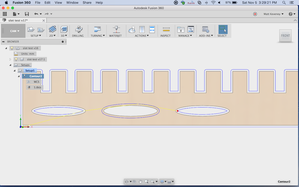
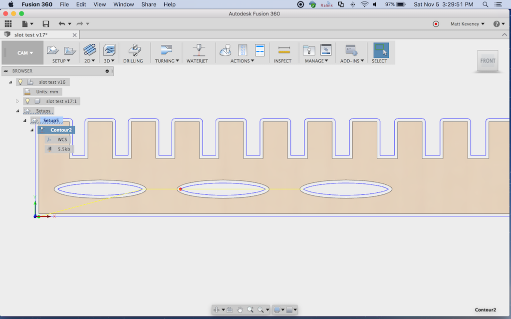
When the tool path looks correct, right-click on setup and choose ‘post process.’
Under ‘settings’:
- Set ‘source’ to ‘personal posts’ (or ‘My Cloud Posts’ if you went that route).
- Set ‘post processor’ to ‘dxf.cps – Autodesk DXF’
- Setting ‘units’ to ‘millimeters’ seems to work properly on our laser. You can use millimeters here even if you designed the project in inches.
Under ‘properties’:
- check ‘only cutting’ This will remove the ‘raise and move’ tool paths.
- Click ‘OK’ and save your DXF file (probably to your network folder, so you can easily access it from the laser cutter’s computer).
Then, import the DXF into the laser as usual. Everything else is still done as taught in our Laser 101 class.
Note on Kerf
The kerf produced by a laser cutter is not perfectly vertical, it’s V-shaped (wider at the top). The kerf will vary in width depending on your material, power and feed settings.
To determine the correct kerf, I recommend cutting a test shape; perhaps a square 20mm on a side. Set the kerf to a reasonable estimate (.2 to .5 mm worked for me, cutting 3 mm baltic birch ply). Then re-generate the tool path and cut using the speed and power settings you will be using for the final piece. If the part measures too small, increase the kerf and retry. If it measures too large, decrease. You should be able to zero-in on the right kerf size for your material’s speed and power settings in just a few tries. Don’t expect perfection, since the kerf can vary even within a single cut due to variations in the material density. I called it good once I got within .1mm.
It should go without saying that you should not scale the cut path inside Lasercut, since that will also scale the kerf adjustment. If you want to make your part bigger or smaller, adjust the model in Fusion 360.
Conclusion
This method should enable you to cut parts to dimensions that precisely match your design. Of course, there’s more to it than that. You have to get the design right to begin with, including appropriate clearances for mating parts. I made the comb-like part illustrated above to experiment with slot sizes; you may want to do something similar with your project.
And I must mention that I don’t think Fusion 360 is the universal design tool for the laser cutter, especially for projects that simply don’t require that level of accuracy.
Designers who identify as artists rather than engineers will probably be much more comfortable with a 2D drawing tool like Illustrator or Inkscape. I recently used Inkscape to model a puzzle project; it would have been a big pain in the neck to do with Fusion 360. Even if you are making parts that must fit together, you can certainly get by with a bit of experimenting, some sanding here and there, and maybe a little extra glue in spots.
I have not yet explored generating separate layers in Fusion 360 for use with engraving or multi-power cutting operations. If you figure that out please write a follow-up post!
Ray came by when I was cutting my first prototype and wondered whether I took care to cut the inside cutouts away before the perimeters. If you don’t do so, the part may fall from the material and shift slightly, causing subsequent cuts on that part to land in the wrong place. I had not done anything special in this regard, but observing the rest of the job, it appears that Fusion did it for me — all interior cuts were performed first. …Or maybe I just got lucky. I’ll ask on the Fusion 360 CAM forum and see if anyone knows.
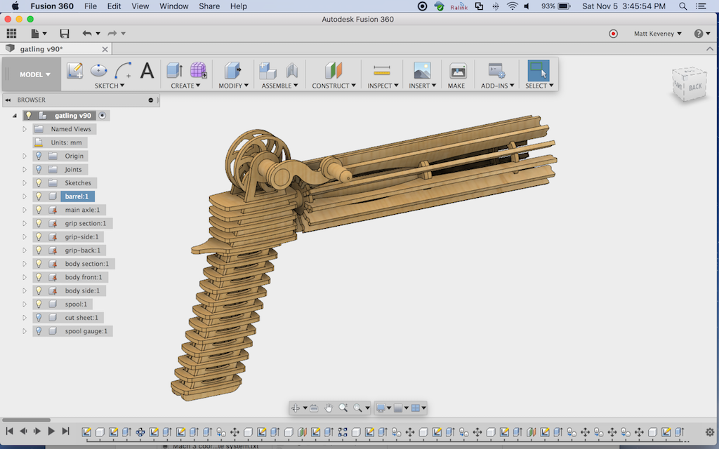
And, if you’re wondering about that cool rubber band gun at the top of the article, I’m afraid you’ll just have to wait for a follow-up post. I have a prototype together, but already have a dozen minor tweaks in mind to make it perfect!

The posts location doesnt seem to work for Mac..
There was no “Autodesk” folder in my user home folder.. I created that structure, but it doesnt work..
There was a “Fusion 360 CAM” folder.. I tried creating a Posts folder in there as well, but that didnt work either..
Any ideas where the .cps files are supposed to go on a Mac for personal posts?
That location works for me using OSX 10.12 and Fusion 2.0.2604. the CPS file is the only thing in that directory, so I might have added that directory myself… I can’t recall.
I found the instructions in this post: http://forums.autodesk.com/t5/hsm-post-processor-forum/where-to-put-cps-files-for-fusion-360/m-p/6093731/highlight/true#M5362
Note: you must select ‘Personal posts’ as the ‘Source’ value in the ‘Post Process’ dialog. That’s the one that’s displayed after clicking “Post process” from the setup menu.
Hope that helps!
Thank you for the info here, it helped a lot. We are using an Epilog Zing laser. Using the DXF post processor works fairly well, wish I could change the line thickness to .001 inches and black. Right now I still have to bring it into Illustrator and make those two changes, then paste it into a templated file in the upper left corner. That being said, it’s better than exporting a DXF layer from a sketch. I’ve tried the post from Epilog, but have not had any success yet.
The dxf.cps file is in fact a javascript program responsible for rendering the dxf file. You should be able to tweak it to change line thickness and color. If you get stuck, ask for help in the Fusion 360 forums. Good luck with it!
Hi, thank you for the article, very helpfull !
I have a question though :
`Copy each body to be laser cut to a new component called ‘cut layout’ or similar. Arrange the parts as desired, generally to minimize waste.`
Is there a way to do this with an integrated function or addin ? I find it really time consuming to rearrange each part in the right direction, align them all on the same plan and then move them on this plan.
Thanks
Yes, it’s a time-consuming pain in the neck!
There’s no built in ‘auto-arrange’ function that I know of. The ‘align’ tool can be quite useful, so look it up if you’re not familiar with it already. I seem to remember a plugin that attempted to help, but it still required a lot of manual input. If you find something let us know!