Category: Metal Working

metal-working

josh in mask

Metal Maestro: Josh Leslie

Introduction

josh in maskJosh originally went to the School of the Arts in Chicago for aerospace engineering, with the intention to learn “how to make things.” But after two years, he realized that the field wasn’t for him. So halfway through his college career, Josh made the decision to switch to industrial design. He later graduated with a degree in object design, which is a similar field to industrial design but is based much more on conceptual design rather than more reality-based and pragmatic design.

After moving to the Bay Area several months ago, Josh found Ace Makerspace completely by chance and decided to join for two main reasons. One reason was that Ace offered easy shop access for a recent graduate itching to do some work. The other is that Josh wanted to share his experience with others and spread the knowledge that he has gained both in college and on his own.

Josh’s Work at Ace

Josh primarily maintains the metal shop and is part of a movement to make the entire space more user-friendly. Right before Josh took over as metal steward, the metal shop at Ace was rearranged by a few other engaged members. The main purpose of this was to make the space more friendly towards a wider range of users rather than only those who were already experienced.

In early August, Ace plans to have the storage area and actual work area flipped in the metal shop room, and Josh is a big supporter (and soon to be facilitator) of this change. As of the writing of this article, when you enter the metal shop you’re immediately met with the member storage space. All of the tools are kept behind all the shelving units in a much smaller area. The idea is to put the tools up-front to make it more user-accessible and to make the metal shop more friendly to the people who walk by it.

In terms of more instructor-oriented work, Josh is part of the Ace movement to change up its teaching style. The new style has three varieties, called Access, Exposure, and Experience-based education. In essence, it’s a 3-part process of learning how to use tools properly, doing something constructive and fun with the tools, and offering more elaborate projects for those seeking more experience. In Josh’s words, “Instead of ‘hey, just cut this block of metal,’ we’re developing project and skill-based classes of varying levels so that you’re not banging nails into a board, you’re actually making something.” One of those ideas was instead of just randomly cutting metal for a class, why not make some basic windchimes that you might actually keep? Another is crafting simple metal jewelry.

Even though Josh has only been at Ace for a few months, he has already made an impact on the community with his friendly personality and willingness to help others. When he isn’t in the metal shop, he can be found helping in mutual aid projects around the Ace space such as the 500 filters project. Keep an eye out for the metal shop revamp later this year.

This article is part of an Ace Makerspace interview series by Carter Jenkins.

Bob’s Guitar Journey

Introduction

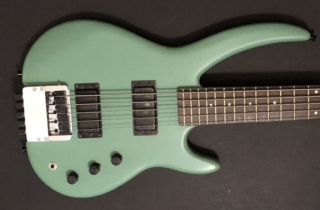
Out of Ace’s list of members, Bob M is definitely one of the more unique people to walk through the workshop doors. Nowadays, Bob is most known for his custom-built guitars and basses, and the reason why this is goes back all the way to his high school days. I’m Carter Jenkins, and I had the chance to speak with Bob about what he does at Ace as well as a little more about how his life has led him to this point.

The Beginning

In high school, Bob originally aimed on becoming a violin craftsman. However, that path didn’t work out and Bob had to explore other areas. For 20 years, Bob held a job as a professional juggler while still exploring his passion for playing guitar. One day in 1989, he paid someone to do some repairs on a bass he had. The job was completely botched, leaving Bob thinking, “I could do so much better than that.” After a little mechanical ingenuity and some tinkering, Bob quickly discovered a new skill.

In the early 90s, Bob opened up a hand-crafted guitar shop to both satisfy his guitar fix and to have a career. Unfortunately, he soon shut down the operation. The money wasn’t the biggest problem, rather Bob “couldn’t stand the sales relationship that the job required.” Wrangling what you love into a money-producing machine isn’t a great feeling, and after only a few years of operation, Bob walked away.

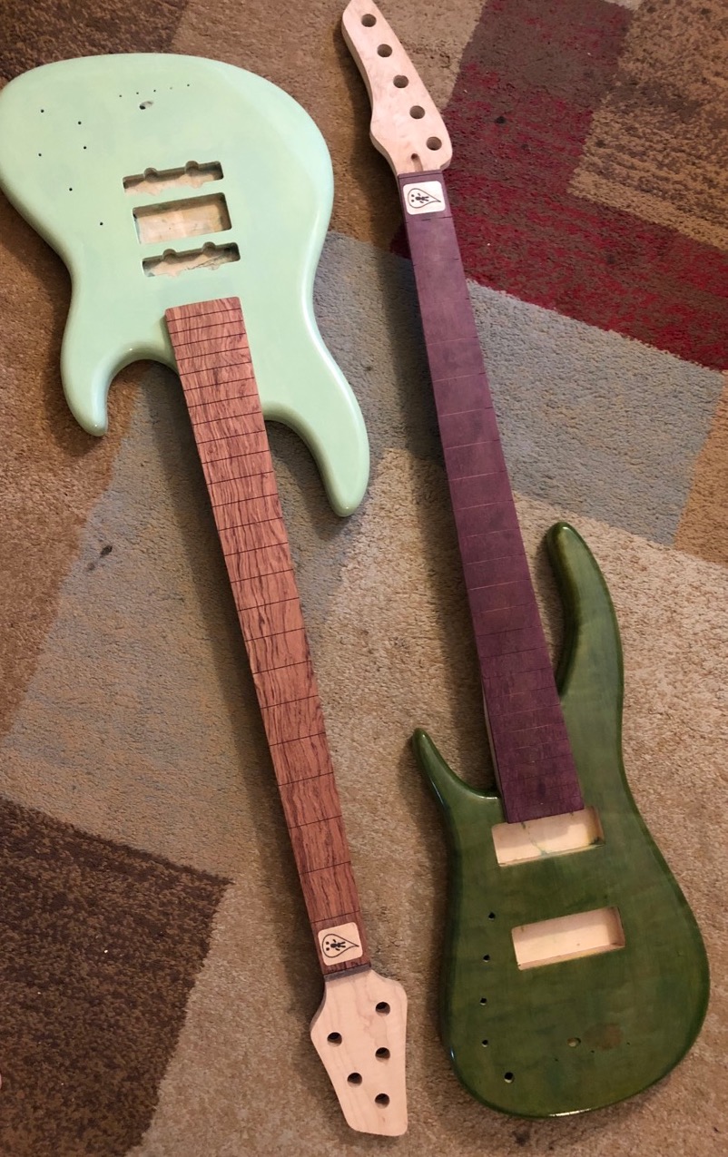
2 partially completed guitars

More Recent Years

In between 1997 and 2017, Bob didn’t do a lot of making or tinkering. However, in 2017, he went to the Ace Building for a Fusion 360 CAD software meeting. During his visit, he took a guided tour around the facility where his attention was caught by the CNC machine and the woodshop. While Ace wasn’t the entire reason he got back into making, seeing the necessary tools that Ace offered with an affordable membership compared to other spaces Bob had looked at was a big part of it. Nowadays, Bob still makes custom guitars, no longer for the money but rather for the affection he has for the craft.

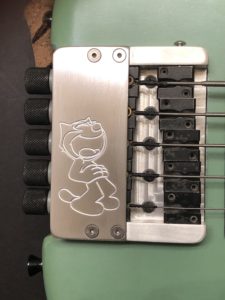
The silver bridge of a guitar with a cartoon character drawn into it
A bridge with a drawing inscribed

Advice for Other makers

Towards the end of our meeting, I asked Bob for any advice he had for makers looking to turn a passion into a business. Bob says that if you have a passion, don’t try to monetize it unless you know you can succeed. Take guitar building for instance. The market for that kind of thing is heavily over-saturated, with new builders investing all their money into a business that will last a few years before shutting down.

Bob got out of the business for a reason, now he spends his days doing what he loves, not doing work. If you have something you want to pursue, he recommends finding a group of people that have a similar interest to you and then finding opportunities to put your skills to work through there. A big enough community will be able to supply you with answers to your questions and will also help you grow as a person.

Big empty room

AMT Expansion 2018

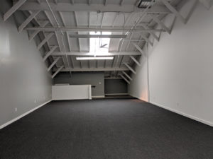
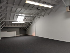
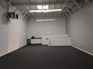
This month AMT turns 8 years old and we are growing! We have rented an additional 1200sqft suite in the building. We have a Work Party Weekend planned June 1-3 to upgrade and reconfigure all of AMT. All the key areas at AMT are getting an upgrade :

CoWorking and Classroom are moving in to the new suite. Rad wifi, chill space away from the big machines, and core office amenities are planned for CoWorking. The new Classroom will be reconfigurable and have double the capacity.

Textiles is moving upstairs into the light. The room will now be a clean fabrication hub with Electronics and 3D Printing both expanding into the space made available. Photo printing may or may not stay upstairs — plans are still forming up.

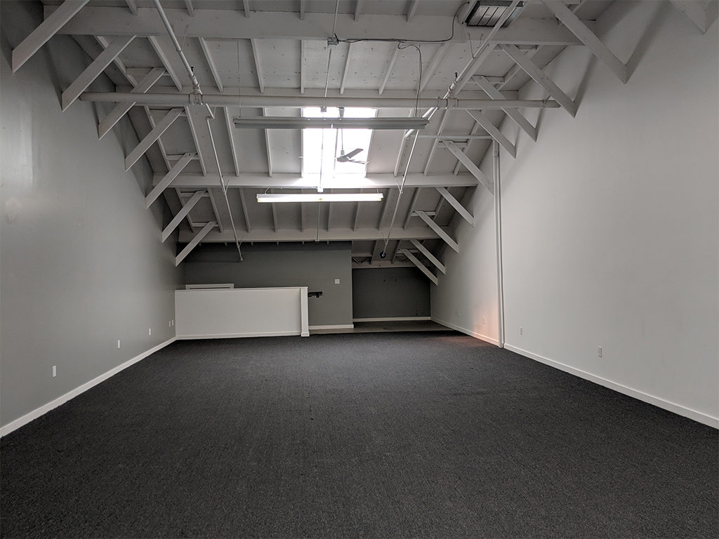
Metal working, bike parking, and new storage including the old lockers will be moving into the old classroom. But before they move in the room is getting a face lift by returning to the cement floors and the walls will get a new coat of paint.

The CNC room and workshop will then be reconfigured to take advantage of the space Metal vacated. We aren’t sure what that is going to look like beyond more workspace and possibly affordable storage for larger short term projects.

Town Hall Meeting May 17th • 7:30PM • Plan the New Space

What expansion means to membership

The other thing that happened in May is after 8 years our rent finally went up. It is still affordable enough that we get to expand. Expansion also means increasing membership volume to cover the new rents and to take advantage of all the upgrades. We are looking to add another 30 members by winter.  Our total capacity before we hit the cap will be 200 members. We feel that offering more classes and the best bargain in co-working will allow us to do this. Please help get the word out!

The New Suite in the Raw

Big empty room

Stirling Engine

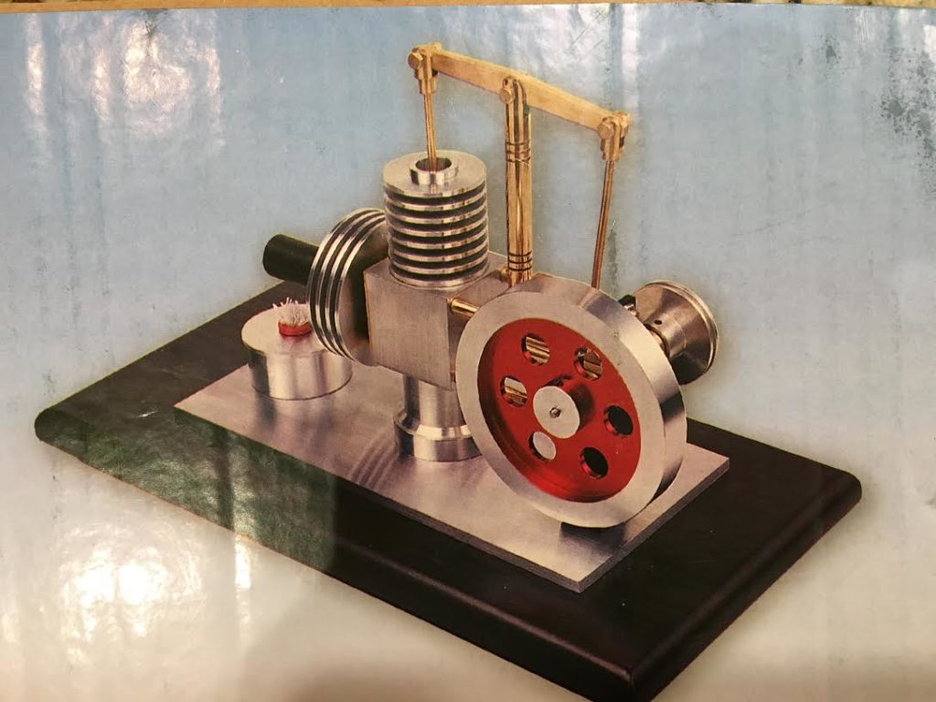
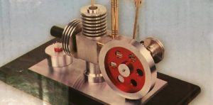
Once upon a time, I bought some plans and materials for a small Walking Beam Stirling Engine. I have seen lots of small home built steam, heat, and even internal combustion engines over the years and thought it would be fun to make one.

Here’s a picture of what it should look like when it is finished

Well, the box with the plans and materials has sat in my garage for 5 years now, and I think it is time to finally get started. So I have made a deal with myself to make a part each week until it is done.It would be an opportunity to really get to know our lathe and milling machine at AMT. I have mostly used bigger, more powerful, and more rigid machine tools at The Crucible, and Techshop. Working with the smaller, lighter machines we have at AMT and how to deal with their limitations will be a learning experience.

This week I was able to make 2 parts.

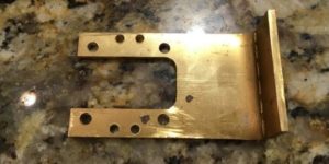
First I made the bracket which supports the crank arm and flywheel shaft. It started out as a 3mm thick brass plate. It needed to be cut to size and shape, and have some precisely positioned holes drilled. It also needed to be bent with a 90 degree angle. It took a bit of thinking about what order to do the operations. The holes need to be a precise height above the platform it all mounts on, and I know that the bend was going to use some of the material up in the curve, but I didn’t know how much. So I decided to “square up” the plate, then bend it, then cut it to shape, and finally drill the holes in the right spots. I used the milling machine to shape, the vise and a hammer to bend, and finally the drill press to do these operations. Here’s a picture of the finished part.

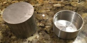
The other part I made was the fuel tank, which is basically a little aluminum cup with a lid and a wick to burn alcohol. This started out as a round bar. On the lathe I “faced” or flattened one end, turned it around, hollowed out the inside of the cup, and finally turned the outside to the final dimensions. Here’s a before and after picture.

So far I am pleased with the results. In hollowing out the inside of the cup I learned that those carbide boring bars that came with our lathe are just too flexible to be useful. But a good sharp HSS tool was able to make clean cuts.

Next I think I will try to make the cylinders. The deep cuts to make the cooling fins look like they may be a challenge to get right.

Brass initials triggering LEDs

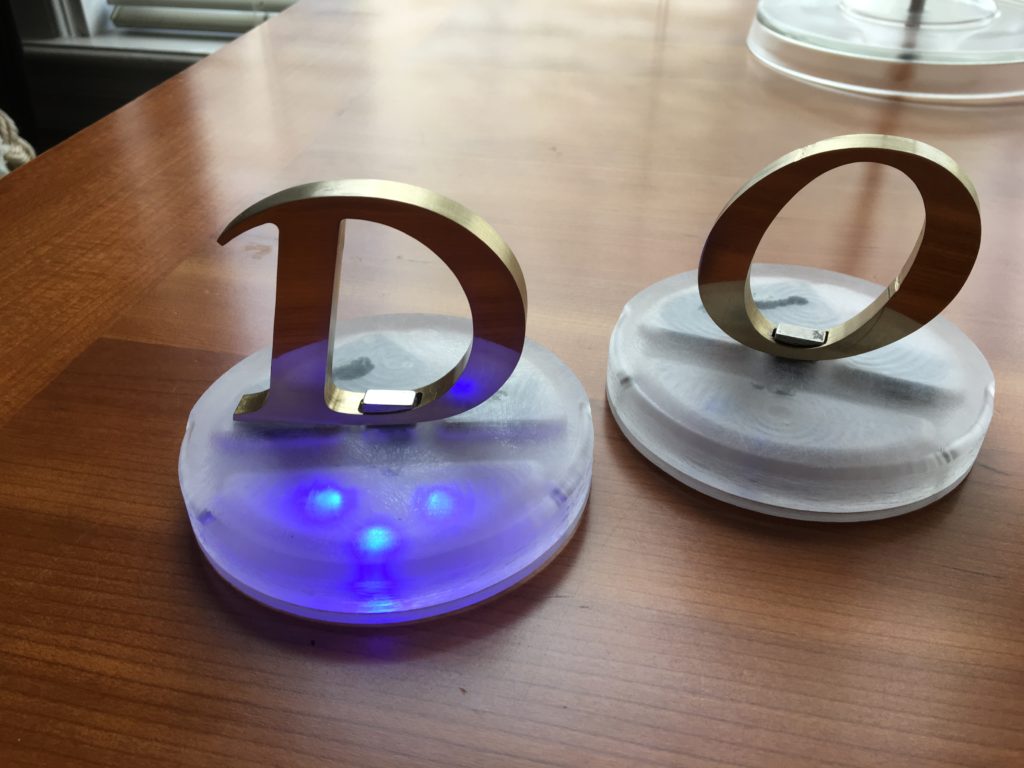
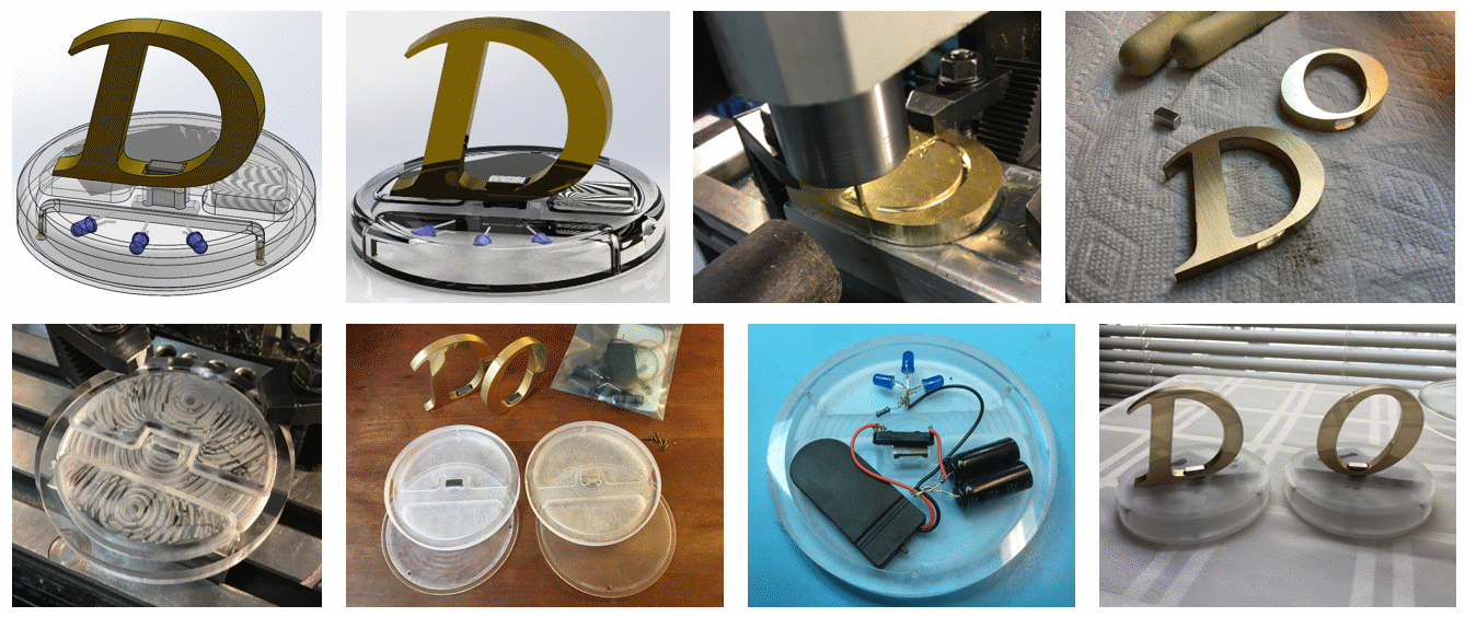
This project, brass initials for my buddy’s kids, was executed entirely at Ace Monster Toys. The brass initials hold a little magnet that triggers a reed switch to light a few LEDs. The brass was machined using AMT’s CNC milling machine with CAM G code generated by SolidWorks (and I’m getting up to speed on the free alternative Fusion360). I broke a few 1/8″ end mills before converging on the right settings: 0.1″ depth of cut, 2500 rpm, and a 3 IPM feed. Dry machining with forced air worked well and was compatible with the way I mounted the brass sheet, which was superglued to an aluminum block. I polished the brass with needle files, sandpaper, and a polishing compound as guided by the fantastic Clickspring videos on Youtube, then dipped the pieces in thinned lacquer.

The base is an acrylic disc that I roughed up with large-grit sandpaper to more evenly diffuse the LED light. Next to the reed switch is a little steel block that gives the magnet something to snap on to. The reed switch switches from a couple CR2032 coin batteries charging two 1.8 mF capacitors to dumping their energy into the LEDs through a 100-ohm resistor. The component are messily hot-glued into place (the step I’m least satisfied with), and there’s a thin back piece that screws on with 1-72 brass screws, which let me practice countersinking.

I only put these in the mail yesterday, so the reaction of the recipients is, as yet, unknown.

16 MB .mov file of operation

3D CNC Milling a new part for an old lathe – part 2

Continuing the saga of the bed bracket for the Monarch 10EE lathe taper attachement, we left off with a nicely squared up rectangular block of metal, and a Fusion 360 model of the part. The next step is to figure out how to hold the work and machine it to shape. I’ve never done much in the way of 3D milling, so this would be a learning adventure for me.

It’s important to think through the sequence of operations, and how for each operation you are going to 1) hold onto the part, and 2) find the origin for your WCS (work coordinate system). For the first setup it’s usually pretty straight forward as you are starting out with a nice rectangular block with flat sides and square corners, just clamp it in the vise, make the top back left corner the origin, and carve away. But then you have to flip the piece over and do the other side and you’ve just cut off all those flat sides and corners, and the vise might not have anything to grab onto. Having the 3D printed version of the part in hand was definitely helpful in visualizing how to do things and in what order.

For this particular part (see http://a360.co/2iXVoIu and part-1), I could choose to start with milling the top or the bottom. There flat areas on the top, one end, and 2 sides of the part which could be used for references. All the critical dimensions are on the bottom, so my first thought was to mill the bottom first and if I screwed it up I wouldn’t waste time milling the top. But thinking about the work holding once the bottom is milled there isn’t much to grab onto any more for milling the top. Only a very small area of the sides are available for clamping. So, looks like I should do the top first, and hopefully there will be enough of the sides left flat for clamping.

In Fusion 360 created my first setup, Since I had already machined the width of my material to size, picked my stock size to be the “model box”. I made the origin the top back left corner of the rectangular block of stock. It’s good to use one of the back corners for this because the rear jaw of a milling vise is fixed that location should stay the same if you take the part out of the vise, flip it around, etc. That back side of the part, and the face of the fixed jaw of the vise are a solid reference point for all the setups. All of your part will be at negative values of y axis. I like to put my origin on the left size, and then all my x axis positions are in the positive direction. If you do this consistently you will be less likely to make mistakes. If you look at the Mach3 toolpath display and things are going into positive Y or negative X, it will look funny, and you should check what is going on.

Drilling the hole in the top seems like a no brainer, so decided to start with that. Long drill bits are wiggly and can wander when starting. So to get an accurately located hole we can use a spotting drill or center drill. They are short and stiff, and will make the hole wherever you put the point to the metal. At AMT we have a bunch of center drills. The problem with these is that if you make a mistake the tiny little tip can break off in your hole and it’s a bear to get it out again. I had just recently experience this, and decided to buy some spotting drills and see how they work. Turns out they work well, and you would really have to screw up bigtime to break one off in the hole. So first operation is a 0.1″ deep spotting drill hole.

Next we need to drill a clearance hole for a 3/8″ bolt. Looking on the chart a close fit clearance hole for a 3/8″ bolt is size W. Oops. No letter size drills at AMT, or in my tool box (add that to the wish list for next year). So, looking at a drill size chart I see that next size up from W is 25/64″ and I do have one of those, so I will use that. Only turns out that when you put the block in vise, and the drill chuck in the mill there isn’t a lot of vertical space left between the bottom of the chuck and the top of the part. The drill is too long and won’t work. Fortunately, the shank of this particular drill bit is turned down to 3/8″, and it fit securely into the R8 3/8″ collect, which doesn’t take up nearly as much vertical space as the drill chuck. The drill fit in the available height, but just barely.

When drilling a deep hole (more than about 4 times the drill diameter) you need to worry about getting the chips out of the hole. The chips can clog up the flutes of the drill bit, jamming it in the hole and causing the bit to break. So when setting up the CAM for this operation, make sure to set the cycle type to “Deep Drilling”. This will cause the drill to go down a bit, then retract out of the hole to clear the chips, then dive back in, drill a little deeper, and repeat until the correct depth is reached.

Unfortunately, in the process of screwing around with the drills, chuck, collets, etc, I somehow (and I’m not really sure how this happened) screwed up my x-axis location. I fired up the g-code and it started drilling the hole in the wrong place. Yikes! Hit E-stop, but it was already in about 1/4″. So much for my beautiful part. Oh well. It’s right next to the real hole, and a nice washer under the bolt head will just cover it from view. Anyway, I re-homed the machine,  used the edge finder to locate the left and back edge of the block, and successfully drilled the hole in the right place.

Next comes carving out the shape of the top of the part. In the CAM software I picked 3D adaptive clearing since I had heard that this was a good way to do this. It uses the whole length of the side of the end mill and side mills off a constant amount of material on each pass. This supposedly removes a lot of material quickly, and improves the life of your cutter since it uses the entire length and not just the tip. And since I didn’t know how well this was going to work I decided to  leave 0.1″ of extra material to clear out on later finishing passes.

One of the parameters for adaptive clearing is the “engagement” of the cutter. This is how much material it will attempt to side mill off on each pass. I was using a 3/4″ end mill, and so I thought I could take pretty big bites, and picked 0.050″. That’s a pretty small fraction of the 0.75 cutter diameter, so why not. Turns out that a 1.7″ depth of cut with that much engagement and that size cutter take a LOT of horsepower to turn, and it puts a lot of force on the machine. When it started to cut the motor immediately stalled out, and the stepper motors started skipping. Argggh. Back to the CAM program, cut the engagement in half to 0.025″. Re-home the machine, re-find the edges, and try again. Boom! Same thing again. Do it all again, but this time try 0.010″. This time it starts to work, but it makes a terrible noise. On no! E-stop again! The bottom of the end mill is cutting the top of the vise jaw! I forgot to check that. Take my part out of the vise, put a parallel underneath, re-find the edges, and try again.

This time it seems to actually be doing the right thing! It’s taking a bit of material off the back of the part going from left to right, but when it gets to the corner and starts to come around it stalls out again. E-stop again! What’s going on? After some thinking it occurred to me that I had used the bounding box of my part for the stock size in my setup, but when I actually cut the metal, I had not accurately cut it to length. I had left a little extra to mill off later. Well the CAM software doesn’t know that metal is there and happily drives the cutter into what it thinks is 0.010″ of metal, but what was really there was 0.1″ of metal. Back to the CAM software and add the extra metal to my stock size, re-home, re-edge find, and try it one more time.

This time it’s working! The big end mill is actually carving out the shape of the top of my part! Time for a celebratory beer? No wait. Taking off only 0.010″ of material on each pass it is going to take about 90 minutes to finish. And long needles of aluminum are flying all over, and so I watch, vacuuming up the mess as it goes until it is finished.
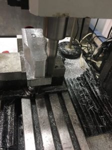
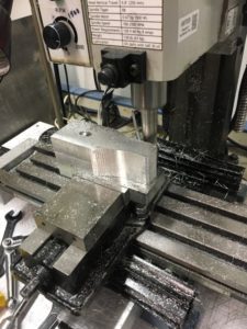
Remember that 0.1″ of material I left in the setup of the adaptive clearing pass? Well now it’s time to take that off. I look at my options in the 3D milling CAM operations and see that “Contour” is a finishing strategy that is good for steep sided things like my shape, so I give that a try.

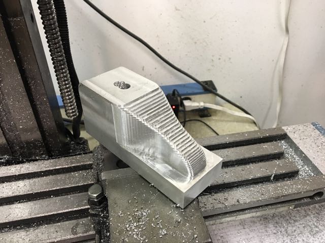
Surprisingly this works with no problems. How can that be? Something that does what I expect the first time? I decide to quit while I am winning and save the rest for another day. Here’s a picture of where I stopped.
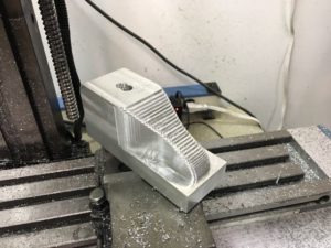
Next steps are to go over the curvy areas of the top with a 3/4″ bull nose end mill, then flip it over, and mill the bottom. That will have to wait until I get back to it a week from now. Stay tuned for part 3.

 

3D CNC Milling a new part for an old lathe – part 1

As some of you know, besides my Tool Steward duties in the ATM Metal Shop, I also have a similar role with the Eastbay Astronomical Society. I help take care of their metal shop located up at Chabot Space & Science Center. One of the key tools up there is a 1964 Monarch 10EE Toolroom Lathe, which was donated by the USDA a few years back.

This is an amazingly accurate and powerful lathe that has all kinds of useful features and functions, one of which is a taper attachment. A taper attachment is an accessory for a lathe that, as the name implies allows one to cut very accurate tapered parts. For example, the tailstock of AMT’s Jet 9×20 lathe has an #2 Morse taper socket into which can be plugged all sorts of centers, drill chucks, drill bits, etc. Unfortunately, one pice of the taper attachment for the Monarch lathe was missing when we got it, and the that has prevented using it. My project is to create a replacement for this part, which is a bracket that securely attaches the sliding part of the taper attachment to the bed of the lathe.

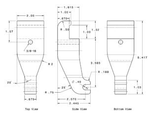
A bit of research on the web found this drawing of what the original looked like

It looks like kind of a complicated part to make, and the material would be expensive, so I decided to try a 3D printed prototype to make sure it will fit. First I created a model in Fusion 360 based on the measurements in the drawing. I haven’t tried this before, but I think you can view the model at http://a360.co/2iXVoIu.
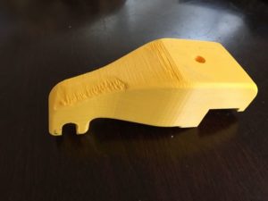
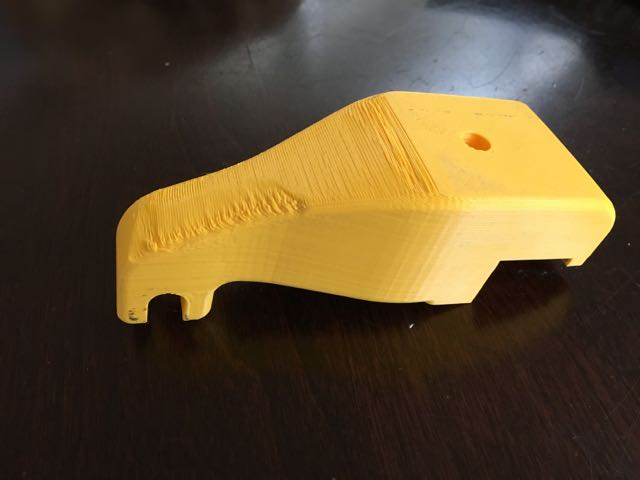
Then I 3D printed it on AMT’s Makerbot. Here’s what I got

I then took this plastic version of the bracket up to the lathe to try it on for size. Good thing I did because it didn’t fit. The arm of the bracket was too long for my lathe and I would have wasted a big chunk of aluminum of I had just dived right in. Perhaps Monarch made multiple versions of the lathe over the years and the plan I found was for a different one? Anyway, I corrected the model, printed out another version and this time it fit perfectly. It’s time to commit to metal!
Drove down to Gorilla Metals in Hayward and bought enough 2″ x 2.5″ Al to make 2 since I figured I would screw up somehow. Also found a bunch of nice materials in their cutoff pile, paid for it all, put the scrap in my car, and drove home, leaving the actual bar I had driven all the way there for on the counter. Next day drove back, and picked it up with some mild ribbing from the friendly folks at the counter.

First thing to do was to cut a 5.5″ piece of the 12″ bar I had brought home. Turns out the 10 TPI blade for the horizontal bandsaw is terribly dull, and after 5 minutes had barely made a dent. Time to order some new blades for that thing. So then moved to the vertical bandsaw to see if that was better. Definitely! Was done in about 5 minutes.

Just like wood from the lumber yard, extruded aluminum bars are not flat and square when you get them, so clamped my raw stock into the milling machine vise, loaded up a fly cutter, and proceeded to flatten and true up all 6 faces making a close to a perfect rectangular block as I  could. The fly cutter left some marks, but not too bad, but it may be time to take a closer look at the tram of our mill. the column seems tilted ever so slightly towards the front. A project for the new year.

Next post will discuss a bit about CAM and workholding for turning this blank into the actual part.

AMT’s Brand New Bit Box! – Initial Build and Glue Up

Working with the CNC routers and the woodshop hand routers/drills frequently, it’s become apparent that AMT needs a new place to store our community bits rather than “randomly in plastic tubs” or “wherever we want”

Enter the brand new AMT Bit Box!

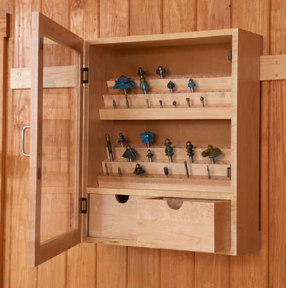
Based on a design found in Woodworking Magazine, the bit box is being made out of dried poplar, some half inch plywood, and a whole lot of quarter inch dowel rods.

The example above isn’t quite the final form. AMT needs less a retail style “display” case and more a functional set of modular shelves that can be changed as its needs change. Additionally, we need a badass logo on the front.

Let’s take a look at the build as it happens!


1. Size Cuts and Dado Cuts

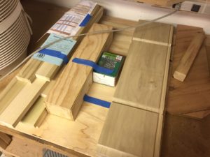
2016-06-29 15.33.10
Click to enlarge!

I didn’t take any pictures of the first few cuts on the table saw, but it’s pretty standard except for one thing: dado cuts. What is a dado cut you ask? Simply put, dado cuts use a special stacked blade system attached to the table saw to cut specifically dimensioned holes, grooves, and end sections. The cool perfectly lined sections you see on the side piece in this first picture are the result of dado cuts!

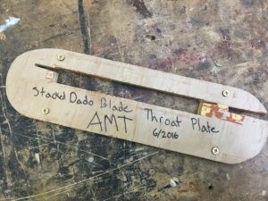
One problem: AMT doesn’t have a throat plate of the appropriate size for dado cuts! OH NO WE CAN’T USE THE TABLE SAW WITHOUT A THROAT PLATE BECAUSE DANGER WHAT CAN WE DO.


2. New Throat Plate for Table Saw!

2016-06-29 15.32.52
Click to enlarge!

Oh wait naw it’s cool guys. I made one really fast, gave it a linseed oil coat and some wax. Now it lives in the shop steward drawer with the other appropriate throat plate sections


2. Checking the Squareness and Design Changes

2016-06-29 16.34.20
Click to enlarge!

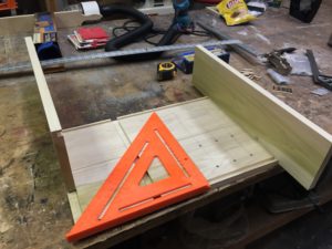
Here’s the pieces of the box being squared and checked for consistency and straightness. Making a GOOD, LEVEL, SQUARE box is actually one of the most difficult things a woodworker can do, which is why it’s such good practice for joinery techniques and other basics. You’ll also notice that by this point I had already drilled the mounting holes for the dowel rods. As I mentioned, I modified the original design to give us a more modular set of shelves to work with. There will still be a standard set of drawers just like in the original picture to hold random objects, but the lower and upper shelves will be removable while the bit holders themselves will rest on the dowel shots like the sleeves of your Ikea bookshelf. Want to make a new bit holder for the latest set of bits you’ve purchased? Need to store a specialized set of objects? Just cut a piece of scrap to size, mount the things you want to put in the box, and drop it on the dowels!


3. Use of Forstner Bits

2016-06-29 16.52.22
Click to enlarge!

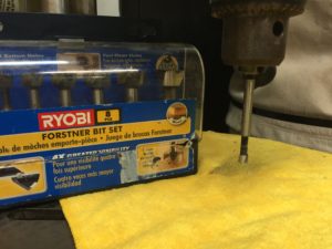
The dowel holes were cut with the Forstner bit set that AMT has in it’s drill section. In the very near future, these might live in the box they were used to make!

For those interested in different types of bits, forstner bits (like any drill bit) makes a hole in wood. BUT WAIT! While a standard drill bit cuts using a spiraled tip, a forstner bit first centers itself using a small needle-like plunge tip and then cuts a very smooth, flat based hole.

To steal from a woodworking site that knows way more than I do: “Because they’re designed to produce a minimum amount of tear-out when exiting the material, Forstner bits are the best bit for drilling through holes. Forstner bits drill a flat-bottomed hole, making them a necessary tool for many hardware installations where a precise depth of mortise is required.”


4. Sandingsandingsandingsaning

2016-06-29 16.34.32
Click to enlarge!

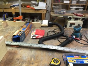
All those big, flat pieces of poplar required about an hour and  half of sanding with three different grits using my finishing sander and its new wonderful connection to the central dust collection system. That hose connector was about $20 at Rockler Wood Supply, while the connector bridging the hose and the central dust intake was about $5. Both were well worth the investment in saving my lungs, the shop air quality, and cleanup in general.

Shopping Link: http://www.rockler.com/dust-right-universal-small-port-hose-kit

Alternatively, you can roll your own using some PVC pipe, our friendly 3D printer, and some standard shopvac hose.


5. Glue Up Finished!

2016-06-29 19.13.50
Click to enlarge!

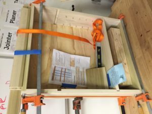
The glue up is finished! Looking at the level, you can see it’s pretty dead close to being straight and square even with the ridiculous clamp job we got going on. Now to come back  and cut/dado the doors, drawers, and bit holders. Look for this to be finished by the end of the week, and to be up on the wall by the end of next week.


Taylor Stein of Autodesk showing off Fusion360

A Great Night of Fusion360

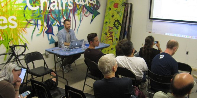
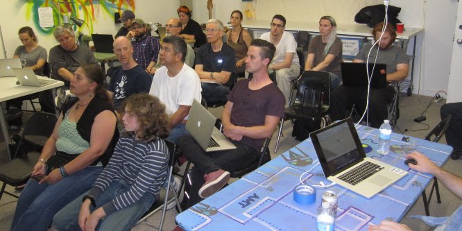
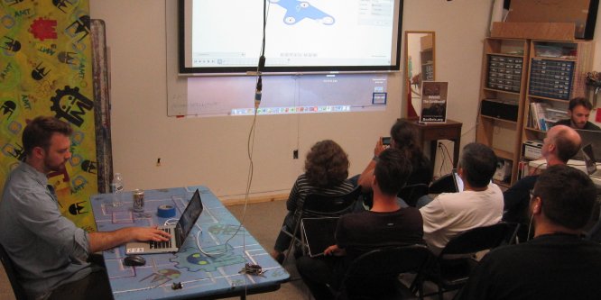
Taylor Stein (@taylor_stein) a Fusion360 evangelist from Autodesk came to AMT to discuss Fusion360, how it works and what it can do for hackerspaces.  We had a full house of over 20 people who had questions about Fusion360 and how best to use it for what they are doing.

full house for the Fusion360 class

Fusion360 covers a wide variety of stuff from laser cutting to CNC routing to 3D printing that there was plenty of questions to be had.

Questions from how to export STL files for 3D printing, 2D layout, parametric variable and more where covered.

Taylor showed the way he teaches layout which is to do a quick sketch of the part and don’t worry about lining the parts up.  After the initial layout, go back and use constraints and dimensions to make the shape just the way you want and the relationships between the various parts stay consistent.  This is a different way of layout where the separate primitives like circles, rectangles and lines are defined in relation with each other so as you change one the others move with it.  For 3D modeling it makes things flow far better than having to go back and change everything after one adjustment.

We covered so much material we never really dived into the 3D CNC CAM side of things so another event was scheduled – Monday July 25th Taylor will be back to talk CNC routing and how to do 3D toolpaths and other CNC related questions.

taylor stein of Autodesk showing off the Fusion

Metalshop Vacuum Fixed

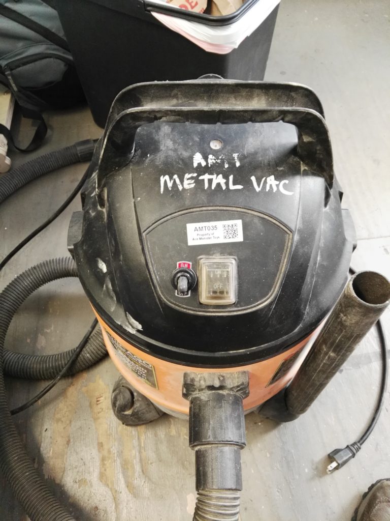
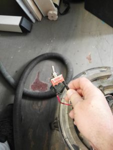
The switch went out in the metalshop vacuum and it has been replaced courtesy of the Electronics Area.  Ignore the old switch and look for the new beefy toggle switch with a rubber dustproof cover that will last longer than the old one or so we can hope.  Vacuum now sucks great again. On/off aluminum signage included at no extra charge.

Š
Š